LTE Architecture and Its Components
The LTE (Long Term Evolution) network architecture is divided into three primary parts:
1. User Equipment (UE)
-
Function: Acts as the end-user device (e.g., smartphone, tablet).
-
Role:
-
Connects to the network via the LTE-Uu interface.
-
Contains a SIM card for authentication and mobility tracking.
-
Sends/receives voice and data services.
-
2. Evolved UMTS Terrestrial Radio Access Network (E-UTRAN)
-
Responsible for wireless communication with UE.
-
Main Component: eNodeB (eNB)
-
Replaces traditional base stations.
-
Functions:
-
Radio Resource Management (power control, scheduling).
-
Mobility Management (handover decisions).
-
Interfaces:
-
S1-MME: Signaling with the MME.
-
S1-U: User data transfer with the SGW.
-
X2: For inter-eNodeB handover and coordination.
-
-
-
3. Evolved Packet Core (EPC)
The EPC handles all data and control functions in the core network.
i. MME (Mobility Management Entity)
-
Manages signaling related to mobility and security.
-
Key functions:
-
UE authentication via the HSS (using the S6a interface).
-
Mobility management and session tracking.
-
S10 interface: Used for handovers between MMEs.
-
ii. SGW (Serving Gateway)
-
Forwards user data packets.
-
Maintains data paths during UE movement across eNodeBs.
-
Connects:
-
To eNB via S1-U
-
To PGW via S5
-
iii. PGW (Packet Data Network Gateway)
-
Provides access to external IP networks like the internet.
-
Allocates IP addresses and enforces QoS.
-
Communicates with:
-
PCRF (via Gx) for policy enforcement.
-
External networks via SGi interface.
-
iv. HSS (Home Subscriber Server)
-
Centralized database.
-
Stores subscriber identity, service information, and security credentials.
-
Communicates with MME using S6a.
v. PCRF (Policy and Charging Rules Function)
-
Controls bandwidth, QoS, and charging rules.
-
Ensures efficient use of resources and enforces policies via the Gx interface.
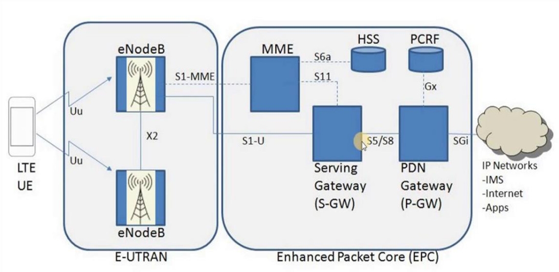
Interfaces in the Diagram
| Interface | Description |
|---|---|
| LTE-Uu | Between UE and eNB (radio link). |
| S1-MME | eNB to MME (signaling). |
| S1-U | eNB to SGW (user data). |
| X2 | Between eNBs for handover. |
| S6a | MME to HSS (authentication). |
| S11 | MME to SGW (session setup). |
| S5/S8 | SGW to PGW (data path). |
| SGi | PGW to external PDNs (Internet). |
| Gx | PGW to PCRF (policy control). |
This structure provides the foundation for LTE’s high-speed data transmission, low latency, seamless mobility, and efficient use of network resources.