Spread Spectrum is a transmission technique in wireless communication, where the
transmitted signal is spread over a wider frequency band than required for traditional
transmission.
Unlike narrowband transmission, spread spectrum is a wideband technology that
enhances signal robustness and security.
This makes the signal more resistant to interference, noise, and eavesdropping.
Why is it used
Interference Resistance – Reduces the impact of noise and jamming.
Security – Difficult to intercept due to signal spreading.
Multiple Access – Allows multiple users to share the same bandwidth eefficiently (e.g., CDMA).
Low Probability of Detection: Appears like noise, making it hard to detect by unintended receivers.
DSSS spreads data by multiplying it with a high-rate pseudo-noise (PN) code (chip sequence).
Each bit becomes multiple chips, increasing bandwidth and interference resistance.
PN code must match at both ends for successful de-spreading.
Offers good security, anti-jamming, and signal reliability.
DSSS Transmitter:
Modulation: User data is modulated using BPSK.
Spreading: Modulated signal is multiplied by a high-rate PN sequence to widen the bandwidth.
Transmission: The spread signal is sent over a carrier; each bit becomes multiple chips, improving resistance to interference.
DSSS Receiver:
De-spreading: The received wideband signal is multiplied again by the same PN sequence used at the transmitter to recover the original narrowband signal.
Demodulation: The de-spread signal is demodulated using BPSK to extract the binary data.
Output: The original user data is reconstructed after filtering and decoding.
Explain Signal propagation in detail. What are various signal propagation effects.
Signal propagation
Signal propagation refers to the movement of electromagnetic waves from a transmitter to a receiver through a medium, influenced by environmental interactions. These interactions cause phenomena like shadowing, reflection, refraction, scattering, and multipath propagation, which significantly impact communication quality.
Types of Signal Propagation Ranges:
Transmission Range:
The range within which the signal is strong enough for the receiver to decode it accurately with a low error rate.
Detection Range:
The range beyond the transmission range where the receiver can sense the signal’s presence but cannot decode the data.
Interference Range:
The range where the signal is too weak to be detected or decoded by a receiver but still strong enough to interfere with other ongoing transmissions.
Key Effects in Signal Propagation
Shadowing
Occurs when large obstacles like buildings or hills block the signal.
Causes a significant drop in signal strength behind the obstacle (known as a shadow region).
Results in slow variations in signal strength over distance.
Reflection
Happens when signals bounce off large surfaces like walls, buildings, or the ground.
Creates multiple copies of the signal arriving at the receiver.
Can either strengthen or weaken the overall signal depending on phase alignment.
Refraction
Bending of the signal as it passes through materials with different densities (e.g., from air to glass or air layers with different temperatures).
Can cause signal distortion and path deviation.
Scattering
Caused by small objects or rough surfaces (e.g., trees, lampposts, street signs).
Signal is diffused in many directions.
Especially significant at higher frequencies like in 5G.
Multi-path Propagation
A combination of reflection, scattering, and diffraction.
Multiple versions of the signal reach the receiver via different paths, each with different delays.
Can cause constructive or destructive interference leading to:
Explain various types of antennas along with their radiation patterns.
Types of Antennas
Types of Antennas and Their Radiation Patterns
Antennas are crucial components in wireless communication, converting electrical signals into electromagnetic waves (transmission) and vice versa (reception). Their radiation patterns define how energy is distributed in space. Below are the key types of antennas and their radiation characteristics:
1. Isotropic Antenna
Radiation Pattern: Spherical (uniform in all directions).
Description:
Hypothetical antenna used as a reference for comparison.
Radiates equally in all directions (360° in 3D space).
Real-world equivalent: Omnidirectional antennas approximate this pattern in 2D (horizontal plane).
Explain the concept of frequency reuse with clustering.
Frequency reuse with Clustering
Frequency Reuse with Clustering in Cellular Networks
1. Concept of Frequency Reuse
Frequency reuse is a fundamental principle in cellular networks that allows the same set of frequencies to be reused in different geographic areas (cells) to maximize spectral efficiency and network capacity. Since radio spectrum is limited, reusing frequencies enables service providers to serve more users without requiring additional bandwidth.
2. Why Frequency Reuse is Needed
Limited Spectrum: The available frequency bands are scarce and expensive.
Interference Management: Reusing frequencies must be done carefully to avoid co-channel interference (interference from cells using the same frequency).
Scalability: Allows the network to expand without needing new frequencies for every cell.
3. Clustering in Frequency Reuse
A cluster is a group of cells that together use the complete set of available frequencies without repetition. The same frequency set is reused in different clusters, spaced far enough apart to minimize interference.
Key Parameters
Cluster Size (K): Number of cells in a cluster.
Determines how often frequencies can be reused.
Common values: K = 3, 4, 7, 12 (depends on network design).
Reuse Distance (D): Minimum distance between two cells using the same frequency to avoid interference.
Calculated as: D=R3K
where ( R ) = cell radius.
Frequency Reuse Factor (1/K): Fraction of total channels available per cell.
Example: K=7 Cluster
Total available frequencies = F
Each cell in the cluster gets F/7 frequencies.
The same frequency set is reused in the next cluster, far enough to prevent interference.
4. Hexagonal Cell Geometry & Reuse Patterns
Cells are typically modeled as hexagons for uniform coverage. The cluster size K follows the equation: K=i2+ij+j2
where i and j are non-negative integers.
Cluster Size (K)
Reuse Pattern
Interference Trade-off
K=3 (i=1, j=1)
High capacity, but high interference
Used in dense urban areas
K=7 (i=2, j=1)
Balanced capacity & interference
Common in GSM networks
K=12 (i=2, j=2)
Low interference, but lower capacity
Used where interference must be minimized
5. How Clustering Reduces Interference
Co-Channel Interference (CCI): Occurs when two cells using the same frequency interfere.
Increasing K → Increases reuse distance (D) → Reduces CCI but decreases capacity.
Decreasing K → Improves capacity but increases interference.
Sectorization (Improving Reuse Efficiency)
Cells are divided into sectors (e.g., 120° directional antennas).
Reduces interference by limiting radiation patterns.
Allows tighter frequency reuse (e.g., K=3 with sectoring).
6. Practical Example (GSM Network)
Total frequencies = 50
Cluster size K=7
Frequencies per cell = 50/7 ≈ 7
The same 7 frequencies are reused in the next cluster, spaced at D=R21 .
7. Advantages of Frequency Reuse with Clustering
Efficient Spectrum Utilization – Same frequencies reused across the network. Scalability – More cells can be added without new spectrum. Interference Control – Proper clustering minimizes co-channel interference.
8. Disadvantages
Trade-off Between Capacity & Interference – Smaller ( K ) increases capacity but raises interference. Complex Planning Required – Optimal ( K ) depends on terrain, user density, and technology.
9. Modern Enhancements (5G & Beyond)
Dynamic Frequency Reuse: AI-based real-time allocation.
Small Cells & Ultra-Dense Networks: More localized reuse.
MIMO & Beamforming: Reduces interference, allowing tighter reuse.
Summary
Frequency reuse enables efficient spectrum usage by reallocating the same frequencies in different cells.
Clustering (K) determines how often frequencies are reused while managing interference.
Trade-offs: Smaller clusters = higher capacity but more interference.
Modern networks use advanced techniques (sectorization, beamforming) to optimize reuse.
This concept is crucial in 2G (GSM), 3G, 4G, and 5G networks to balance coverage, capacity, and interference.
What are various advantages and disadvantages of small cells in cellular systems.
Advantages and disadvantages of small cells in cellular systems.
Small cells (e.g., femtocells, picocells, microcells) are low-power, short-range wireless access points that enhance network capacity and coverage in high-demand areas. They play a crucial role in 4G LTE and 5G networks. Below are their key advantages and disadvantages:
Advantages of Small Cells
1. Improved Network Capacity
Higher Data Rates: Small cells offload traffic from macrocells, reducing congestion.
Increased Spectral Efficiency: Frequency reuse is optimized due to smaller coverage areas.
2. Enhanced Coverage & Signal Quality
Better Indoor Penetration: Ideal for homes, offices, and dense urban areas.
Reduced Dead Zones: Fills gaps where macrocell signals are weak.
3. Energy Efficiency
Lower Power Consumption: Small cells consume less energy than traditional macrocells.
Greener Networks: Reduced carbon footprint compared to large base stations.
4. Cost-Effective Deployment
Lower Infrastructure Costs: Cheaper to install and maintain than macrocells.
Flexible Placement: Can be mounted on lampposts, buildings, and street furniture.
5. Support for 5G & IoT
Ultra-Low Latency: Critical for 5G applications (e.g., autonomous vehicles, AR/VR).
Cost & Scalability Issues: Deploying fiber to every small cell is expensive.
4. Security & Privacy Concerns
Vulnerable to Physical Tampering: Easier to hack or damage than secured macrocell sites.
Potential for Unauthorized Access: Requires strong encryption and authentication.
5. Regulatory & Zoning Challenges
Permitting Issues: Local regulations may restrict installations (e.g., on historic buildings).
Public Resistance: Aesthetic concerns (“cell tower clutter”).
6. Limited Range
Short Coverage Area (~100m–2km): Not suitable for rural or wide-area coverage.
Conclusion
Small cells are essential for 5G and dense urban networks but require careful planning to mitigate interference, backhaul, and deployment challenges. They complement (rather than replace) macrocells, forming a heterogeneous network (HetNet) for optimal performance.
Co-Channel Interference (CCI) in Wireless Networks
Co-Channel Interference (CCI) occurs when two or more cells (or transmitters) in a cellular network use the same frequency channel, causing their signals to interfere with each other at the receiver. This interference degrades signal quality, leading to:
📉 Reduced data rates
📶 Poor call quality (dropped calls)
🔄 Higher error rates in transmission
Causes of Co-Channel Interference
Frequency Reuse
Cellular networks reuse the same frequencies in different cells to maximize spectrum efficiency.
If the reuse distance (D) is too small, signals from distant cells using the same frequency overlap.
High Transmitter Power
Strong signals from faraway cells may overpower nearby signals on the same frequency.
Poor Antenna Design
Omni-directional antennas radiate signals in all directions, increasing interference risk.
Directional/sector antennas help reduce CCI.
Cell Overlap in Dense Networks
Small cells (e.g., femtocells, picocells) increase interference risk due to tight frequency reuse.
How CCI is Measured
The Carrier-to-Interference Ratio (C/I) quantifies CCI: C/I=Interfering Signal Power (I)Desired Signal Power (C)
Good C/I: ≥ 18 dB (for acceptable voice quality in GSM).
Poor C/I: < 12 dB (causes noticeable degradation).
Techniques to Reduce CCI
Method
How It Works
1. Frequency Planning
Assign frequencies to cells so that co-channel cells are far apart (large reuse distance D).
2. Sectorization
Use directional antennas (e.g., 120° sectors) to limit interference.
3. Power Control
Reduce transmission power in small cells to minimize overlap.
4. Cell Splitting
Divide large cells into smaller ones (micro/pico cells) with lower power.
5. Advanced Modulation
Use CDMA (Code Division Multiple Access) or OFDMA (Orthogonal FDMA) to separate signals.
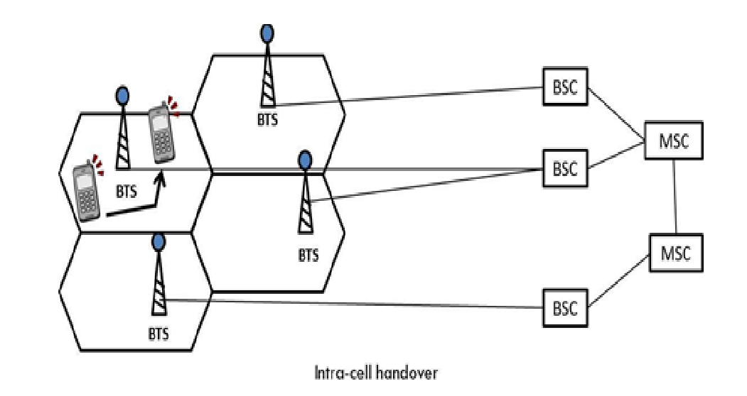
When a mobile user is engaged in conversation, the MS (Mobile Station) is connected to the BTS (Base Transceiver Station) via radio link. If the mobile user moves to the coverage area of another BTS, the radio link to the old BTS is eventually disconnected, and a radio link to the new BTS is established to continue the conversation. This process is called handover or handoff.
There are four types of handovers in GSM
1. Intra-Cell Handover
Occurs within the same cell but between different frequency channels or time slots.
Used to reduce interference or improve signal quality.
Example: A call remains in the same base station but switches to a different frequency
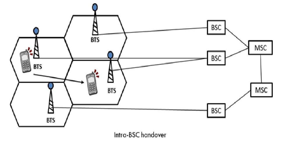
2. Inter-Cell Handover (Intra-BSC Handover)
Occurs between two cells controlled by the same Base Station Controller (BSC).
The Mobile Station (MS) moves from one Base Transceiver Station (BTS) to another, but the BSC remains unchanged.
Example: A user moving from one cell to another within the same city under the same BSC.
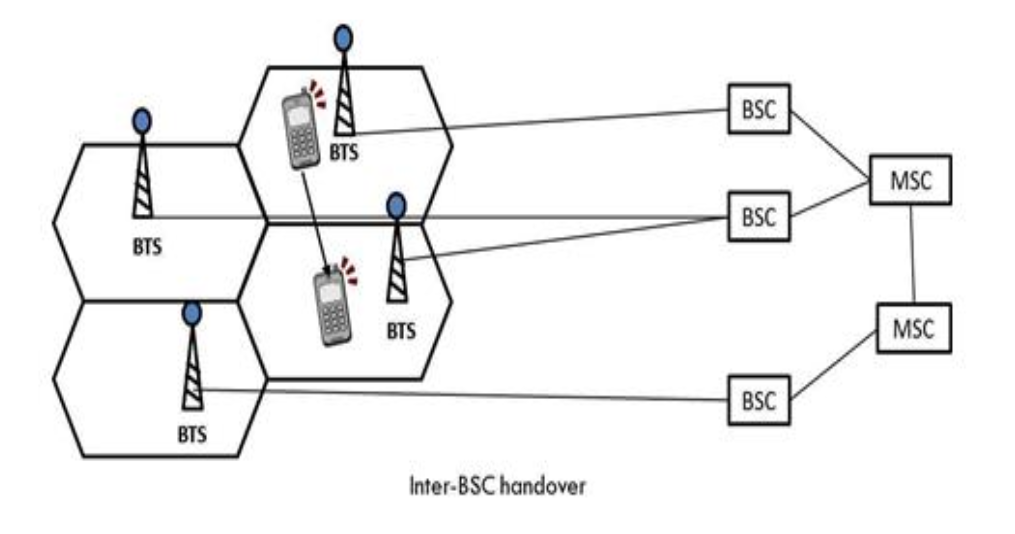
3. Inter-BSC Handover
Happens when a call is transferred between two different BSCs but within the same Mobile Switching Centre (MSC).
The MSC manages the handover process to ensure a smooth transition.
Example: A user moves from one city area to another, and the call is handled by a different BSC.
4. Inter-MSC Handover
Occurs when the mobile user moves between two different MSCs.
Requires coordination between the two MSCs to transfer the call.
Example: A person traveling between different states or large regions.
Explain Security algorithms used in GSM for authentication and privacy (A3, A5, A8).
Security algorithms used in GSM for authentication and privacy (A3, A5, A8)
Overview
GSM uses several cryptographic algorithms to ensure authentication, confidentiality, and privacy of the communication between a mobile station (MS) and the network.
The key algorithms are:
A3 — used for authentication
A8 — used for generating the session key
A5 — used for encrypting the communication (privacy)
1. A3 Algorithm (Authentication)
Purpose: Verify the identity of the mobile subscriber to the network.
How it works:
The SIM card and the network both share a secret key called Ki (individual subscriber authentication key).
When the MS tries to connect, the network sends a random challenge number called RAND.
The SIM applies the A3 algorithm to RAND and Ki, producing a Signed Response (SRES).
The MS sends the SRES back to the network.
The network computes the expected SRES using its copy of Ki and RAND.
If the two SRES values match, the subscriber is authenticated.
Example implementation: The most widely used A3 algorithm is COMP128.
2. A8 Algorithm (Session Key Generation)
Purpose: Generate the ciphering key used to encrypt the communication.
How it works:
Like A3, it takes the Ki and the same RAND as inputs.
It outputs a 64-bit session key (Kc).
This session key Kc is used for encrypting/decrypting the over-the-air data.
Typically, A3 and A8 are implemented together in COMP128, so they run simultaneously with the same inputs.
3. A5 Algorithm (Encryption/Privacy)
Purpose: Encrypt the actual communication between MS and base station to protect confidentiality.
How it works:
Uses the session key Kc generated by A8.
Encrypts the voice and data over the air interface using a stream cipher.
There are different versions of A5 with varying strength:
A5/1: Stronger encryption, used mainly in Europe.
A5/2: Weaker encryption, used in some countries due to export restrictions.
A5/3: A newer, stronger encryption algorithm based on Kasumi block cipher.
Encryption ensures that anyone eavesdropping cannot easily understand the transmitted data.
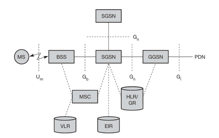
General Packet Radio Service (GPRS) is a packet-oriented mobile data service that enhances GSM networks by enabling efficient, always-on Internet connectivity and data transmission. Unlike traditional circuit-switched GSM services, GPRS allows for packet switching, which improves bandwidth utilization and supports data applications such as web browsing, email, and multimedia messaging.
GPRS Architecture Components
1. Mobile Station (MS)
The user’s mobile device (phone, tablet).
Communicates with the network using the Um interface (radio link).
2. Base Station Subsystem (BSS)
Includes Base Transceiver Station (BTS) and Base Station Controller (BSC).
Handles radio communication with the MS.
Uses the Gb interface to connect to the SGSN.
3. Mobile Switching Centre (MSC)
Handles traditional voice calls, SMS, and circuit-switched services.
Works alongside SGSN to provide integrated voice and data services.
4. Serving GPRS Support Node (SGSN)
Manages packet-switched data services for mobile users.
Responsible for mobility management, authentication, and data packet forwarding.
Explain Mobile Terminated Call and Mobile Originated Call in detail.
Mobile Terminated Call and Mobile Originated Call
Mobile Terminated Call (MTC)
An MTC refers to a call received by the mobile user. When a caller dials a mobile number, the GMSC (Gateway MSC) queries the HLR to locate the mobile subscriber. After locating the serving MSC and BSS, the network pages the MS, performs authentication, and sets up the call.
Steps:
1–2): Calling user dials MS number → Call reaches GMSC via PSTN.
An MOC is a call initiated by the mobile user. The MS sends a request to the BSS, which forwards it to the MSC. The MSC then authenticates the user with the VLR and routes the call through the GMSC to reach the PSTN or other network.
Steps:
1): MS sends a request to BSS to make a call.
2): BSS forwards the request to MSC.
3–4): MSC authenticates MS with VLR.
5): Call setup proceeds from MSC to GMSC.
6–7): GMSC routes the call to PSTN (or other networks).
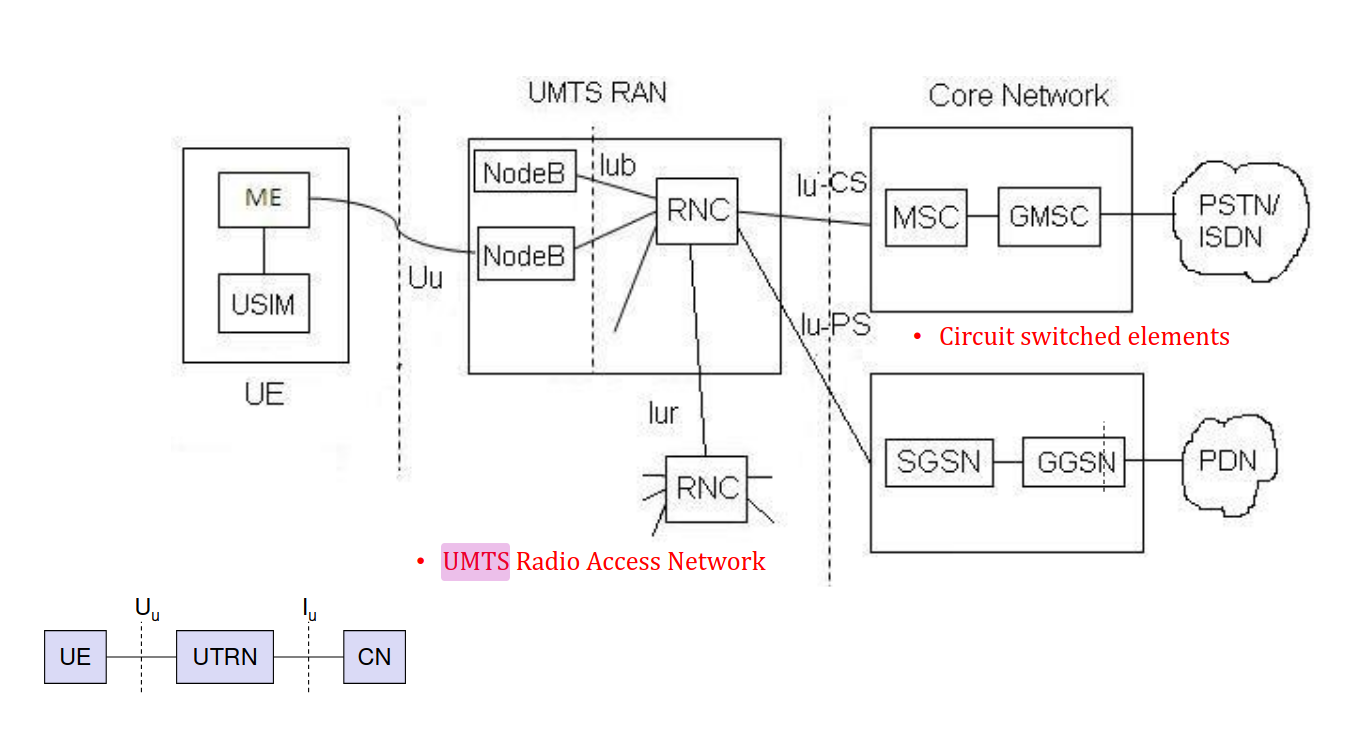
UMTS Architecture (Universal Mobile Telecommunications System)
UMTS is a 3rd Generation (3G) mobile communication system that enhances GSM by offering higher data rates, multimedia services, and improved capacity. It is based on a new radio access technology (W-CDMA) and integrates with the existing GSM core.
What are the roles of EIR and HLR entities in a GSM network.
Roles of EIR and HLR in GSM Network
Equipment Identity Register (EIR)
The EIR is a database that maintains records of mobile devices based on their IMEI (International Mobile Equipment Identity) numbers.
Functions of EIR:
Device Authentication:
Verifies the IMEI of a mobile device before allowing it to connect to the network.
Maintaining Device Lists:
Whitelist: Devices allowed to access the network.
Greylist: Devices under monitoring (e.g., malfunctioning or suspicious devices).
Blacklist: Devices banned from the network due to theft, fraud, or other issues.
Home Location Register (HLR)
The HLR is a central database that stores permanent subscriber information required for authentication, call routing, and roaming. It works in coordination with the VLR (Visitor Location Register) and MSC (Mobile Switching Centre) to track and manage users.
Functions of HLR:
Subscriber Information Storage:
Maintains IMSI (International Mobile Subscriber Identity), MSISDN (phone number), service subscriptions, and authentication keys.
Location Management:
Keeps track of the current location of subscribers by storing the identity of the VLR where they are currently registered.
Authentication and Security:
Works with the AuC (Authentication Centre) to verify subscribers and prevent unauthorized access to the network.
CDMA (Code Division Multiple Access) is a channel access method used in wireless communication systems that allows multiple users to share the same frequency band simultaneously, unlike methods such as FDMA or TDMA that divide access by frequency or time.
Key Concepts:
Spread Spectrum Technique: CDMA spreads each user’s signal over a wide frequency band using a unique pseudo-random code.
Unique Codes for Each User: These codes enable the receiver to distinguish between different users transmitting on the same frequency simultaneously.
Simultaneous Access: Multiple users can access the channel at the same time without causing interference to each other.
Advantages:
Efficient Bandwidth Usage: Allows more users to share the same bandwidth without signal collisions.
Better Signal Quality: Provides strong resistance to noise and interference, resulting in improved call quality.
Improved Privacy: Unique coding of signals makes eavesdropping difficult, enhancing security.
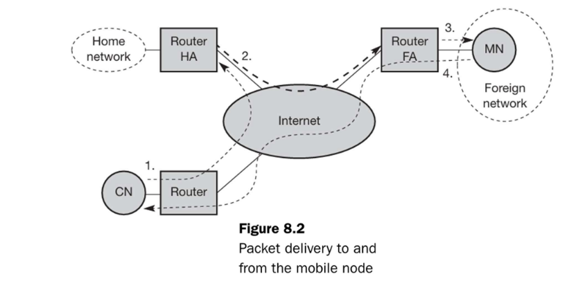
Explain packet delivery mechanism to and from mobile node with the help of Mobile IP network diagram.
Packet delivery mechanism to and from mobile node
Entities Involved:
MN (Mobile Node): Your device that’s moving.
CN (Correspondent Node): The device MN is talking to.
HA (Home Agent): The router on MN’s home network.
FA (Foreign Agent): The router on the network MN is visiting.
CoA (Care-of Address): MN’s temporary address in the foreign network.
A. Packet Delivery TO the Mobile Node (from CN to MN)
Imagine the arrows showing the data flow. (See diagrams on page 31 and page 33 )
CN → HA (Packet to Home Network)
The CN sends a packet.
Destination IP: MN’s permanent Home Address.
Source IP: CN’s Address.
CN ===> Internet ===> HA
This packet travels through the internet and, using standard routing, arrives at the MN’s Home Network, where the HA intercepts it (often using Proxy ARP). The HA knows the MN is not at home.
HA → FA (Tunneling to Foreign Network)
The HA takes the original packet from the CN.
It encapsulates this original packet inside a new IP packet. This is called tunneling.
Outer (New) Header - Source IP: HA’s Address.
Outer (New) Header - Destination IP: MN’s current Care-of Address (COA), which is often the FA’s address.
Inner (Original) Header - Destination IP: MN’s Home Address.
HA ====> (Tunnel through Internet) ====> FA
The HA sends this encapsulated packet to the FA.
FA → MN (Delivery in Foreign Network)
The FA receives the encapsulated packet from the HA.
The FA decapsulates it, removing the outer header and retrieving the original packet.
The FA now sees the original packet (Destination IP: MN’s Home Address; Source IP: CN’s Address).
FA ===> MN
The FA forwards this original packet to the MN on the foreign network.
B. Packet Delivery FROM the Mobile Node (MN to CN)
Imagine the arrows for the return path. (See diagram on page 32 )
MN → FA → CN (Directly to Correspondent Node)
The MN wants to send a packet to the CN.
Source IP: MN’s permanent Home Address.
Destination IP: CN’s Address.
MN ===> FA ===> Internet ===> CN
The MN sends the packet. Typically, the FA acts as the MN’s default router in the foreign network.
The FA receives the packet from the MN and routes it normally through the internet towards the CN. The packet does not necessarily need to go through the HA in this direction (unless reverse tunneling is used, which is an optimization).
What is Snooping TCP? What are its advantages and disadvantages.
Snooping TCP
Overview
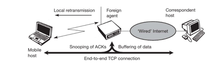
Snooping TCP is a TCP-aware link-layer protocol employed in wireless networks to enhance TCP performance over unreliable wireless links. It is implemented at the base station, where it monitors TCP packets (both data and acknowledgments) that pass through it. Traditional TCP interprets all losses as congestion, leading to unnecessary retransmissions and reduced performance. Snooping TCP helps mitigate this by handling retransmissions locally without unnecessarily involving the sender.
Working Mechanism:
The mobile host communicates with a correspondent host via a foreign agent (such as a base station or router). The TCP connection is end-to-end between the mobile host and the correspondent host. The foreign agent “snoops” or monitors TCP ACKs from the mobile host and buffers TCP data packets sent from the correspondent host to the mobile host. If an ACK is not received within a certain time (indicating possible loss), the foreign agent locally retransmits the buffered data to the mobile host without involving the sender.
Advantages of Snooping TCP:
Maintains End-to-End Semantics: The end-to-end TCP connection remains intact.
Local Recovery: Wireless link errors are corrected quickly by the base station without involving the sender.
Automatic Fallback: The approach automatically falls back to standard TCP if the enhancements stop working.
No Correspondent Host Changes: The correspondent host does not need to be changed, as most enhancements are in the foreign agent.
No Mobile Host Changes (for one direction): Supporting only the packet stream from the correspondent host to the mobile host does not require changes in the mobile host.
Disadvantages of Snooping TCP:
Not Fully Transparent: Requires additional support like Negative Acknowledgments (NACK) at the mobile host, which can break transparency.
Wireless Link Dependency: Performance is dependent on the wireless link; delays may trigger unnecessary retransmissions.
Explain Mobile TCP with their merits and demerits.
Mobile TCP with their merits and demerits
Mobile TCP (M-TCP)
Mobile TCP (M-TCP) is a variant of TCP specifically designed to improve performance over wireless and mobile networks. As mobile networks present unique challenges that standard TCP wasn’t designed to handle, M-TCP addresses these issues while maintaining TCP’s core end-to-end connection semantics.
How Mobile TCP Works
M-TCP employs a split-connection approach:
The connection is split at the Foreign Agent (FA) - typically located at the boundary between fixed and wireless networks
The segment between the Correspondent Host (CH) and the FA uses standard TCP protocols
The segment between the FA and the Mobile Host (MH) is managed differently to accommodate the characteristics of wireless networks
During disconnections or handovers, the FA can pause the connection to prevent unnecessary congestion control mechanisms from activating
When the mobile host temporarily disconnects or experiences poor connectivity:
The FA advertises a zero window size to the fixed host
This effectively freezes the connection without triggering TCP’s congestion control
When connectivity is restored, transmission can continue from where it left off
Merits of Mobile TCP
Preservation of End-to-End TCP Semantics: Unlike some other wireless TCP solutions, M-TCP maintains the original TCP connection semantics between sender and receiver.
Effective Handling of Disconnections: M-TCP avoids unnecessary retransmissions by stopping data transmission when the mobile device is temporarily unreachable, preventing network congestion.
Support for Smooth Handovers: The protocol can handle switching between networks without breaking the connection, making it ideal for mobile scenarios where users move between different cells or networks.
Prevention of Timeout: By freezing the connection rather than allowing it to time out, M-TCP avoids the overhead of establishing new connections after brief disconnections.
Bandwidth Efficiency: Prevents unnecessary packet transmissions during periods of disconnection, conserving bandwidth on both fixed and wireless networks.
Demerits of Mobile TCP
Complex Foreign Agent Requirements: Requires additional logic and control mechanisms at the base station or foreign agent, increasing implementation complexity.
Limited Deployment: Not widely supported or implemented in current networks, requiring special setup and configuration.
Potential for Increased Delays: Pausing connections during movement between networks can introduce additional latency in data transmission.
Infrastructure Dependency: Relies on network infrastructure support, making it difficult to deploy in heterogeneous network environments.
No Local Error Recovery: Unlike some other mobile TCP variants (such as Snooping TCP), M-TCP doesn’t implement local error recovery mechanisms for wireless transmission errors.
Comparison with Other Mobile TCP Enhancements
In the context of other TCP enhancements for mobile environments:
Indirect TCP (I-TCP): Completely breaks the end-to-end connection semantics, while M-TCP preserves them
Snooping TCP: Focuses on local retransmissions without modifying TCP’s behavior, while M-TCP actively manages the connection state
Transmission/Time-out Freezing: Similar to M-TCP’s approach but with different implementation details
Selective Retransmission: Complements M-TCP’s approach by optimizing what data gets retransmitted
Mobile TCP represents an important approach to handling the unique challenges of mobile networking while maintaining compatibility with the core principles of TCP’s reliable connection-oriented design.
What do you mean by hidden and exposed station problem. How can they be avoided.
Hidden and Exposed Station Problems in Wireless Networks
Hidden and Exposed Station Problems in Wireless Networks
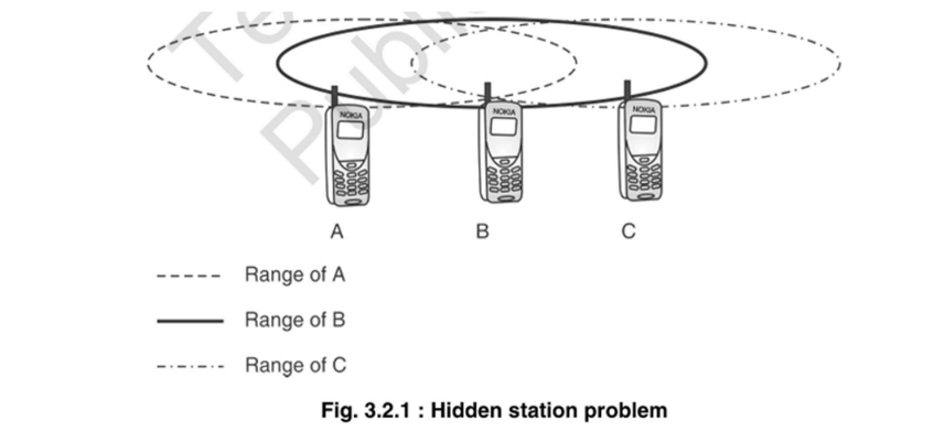
1. Hidden Station Problem
Definition: Occurs when two stations (e.g., A and C) are out of range of each other but both can communicate with a common station (e.g., B).
Problem:
Station A senses the channel as idle and sends data to B.
At the same time, station C (which cannot sense A) also sends data to B.
Collision occurs at B, even though A and C could not detect each other.
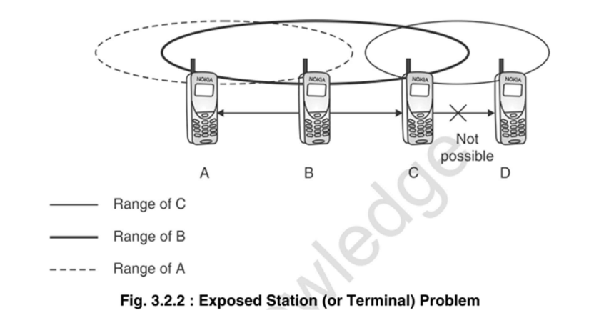
As shown in the figure, stations A and C cannot detect each other’s transmissions because they are outside each other’s range (indicated by the dashed and dash-dot lines). However, both are within range of station B (solid line).
Result:
Increased collisions and reduced network performance.
Higher packet loss rate.
Reduced overall throughput.
Increased latency due to retransmissions.
Solution:
Use RTS/CTS (Request to Send / Clear to Send) mechanism from IEEE 802.11 MAC protocol.
Station A sends an RTS to B; B replies with CTS.
CTS is heard by all nearby nodes (including C), so C stays silent, preventing collision.
The duration of the intended communication is included in both RTS and CTS frames.
2. Exposed Station Problem
Definition: Occurs when a station (e.g., C) refrains from transmitting due to sensing a nearby transmission (e.g., B → A), even though its transmission (C → D) would not interfere.
Problem:
B senses the channel and finds it free. B starts transmitting data to A.
C also wants to transmit data to D.
C detects B’s transmission, because B is within C’s transmission range.
C assumes the channel to D is busy and delays its transmission, even though:
D is out of range of B’s signal.
There would be no interference between B→A and C→D communication.
Result:
Underutilization of the channel — reduced throughput.
Unnecessary delays in data transmission.
Inefficient use of network capacity.
Reduced overall network performance.
Solution:
Use RTS/CTS Mechanism:
C sends RTS to D.
If D replies with CTS, it means the channel is clear for communication.
Since D is not in range of B, it will respond, allowing C to send.
This prevents C from unnecessarily delaying its transmission.
Write a short note on: Agent Advertisement and Agent Discovery.
Agent Advertisement and Agent Discovery in Mobile IP
Agent Advertisement and Agent Discovery are key processes in Mobile IP that enable mobile nodes to detect their network location and communicate with Home and Foreign Agents.
Agent Advertisement
Agent Advertisement is an extension of ICMP Router Advertisements that helps mobile nodes determine their network location. Home Agents (HA) and Foreign Agents (FA) periodically broadcast these messages into their physical subnets.
Key characteristics:
Uses Extended ICMP Router Advertisements (type 9)
Contains information about available Care-of Addresses (COAs)
Includes several flag bits indicating agent capabilities:
R: Registration required
B: Busy, no more registrations
H: Home agent
F: Foreign agent
M: Minimal encapsulation support
G: GRE encapsulation support
T: Foreign agent supports reverse tunneling
The advertisement message structure includes:
Type and code fields
Number of addresses being advertised
Lifetime (validity period)
Preference levels for each address
Router addresses
Available Care-of Addresses
Agent Discovery
Agent Discovery is the process through which a Mobile Node (MN) listens to Agent Advertisement messages to:
Detect whether it’s in its home network or a foreign network
Obtain a Care-of Address (COA) from Foreign Agent advertisements
Determine the capabilities of available agents
Initiate the registration process with appropriate agents
This discovery mechanism is essential for network integration in mobile environments as it allows mobile nodes to maintain connectivity while moving between different networks without changing their IP addresses.
After discovery and obtaining a COA, the mobile node can register with its Home Agent (with a limited lifetime), enabling proper packet routing regardless of the node’s physical location.
Explain Tunnelling and Encapsulation in brief. What are the various types of Encapsulation techniques.
Tunnelling and Encapsulation
Tunneling and Encapsulation in Mobile IP
Tunneling
Tunneling is a communication protocol that allows data movement from one network to another by exploiting encapsulation. It creates a virtual pipe for data packets between a tunnel entry point (like a Home Agent) and a tunnel endpoint (like a Care-of Address). This enables private network communications to be sent across public networks while potentially hiding the nature of the traffic.
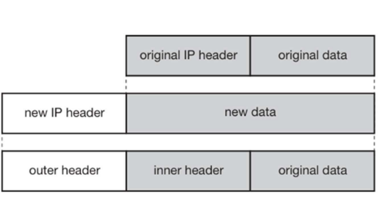
Encapsulation
Encapsulation is the mechanism of taking a packet (consisting of a packet header and data) and putting it into the data part of a new packet. In simpler terms, encapsulation means sending a packet through a tunnel. The reverse process - extracting the original packet from the data part of another packet - is called decapsulation.
In Mobile IP, the Home Agent (HA) takes the original packet destined for the Mobile Node (MN), puts it into the data part of a new packet, and sets up a new IP header (outer header) to route the packet to the Care-of Address (COA).
Types of Encapsulation Techniques
1. IP-in-IP Encapsulation (RFC 2003)
Mandatory implementation in Mobile IP
Creates a tunnel between HA and COA
The outer header contains:
Source: IP address of HA
Destination: Care-of Address
Protocol type: IP-in-IP
The inner header remains unchanged (original packet)
Simple but effective method
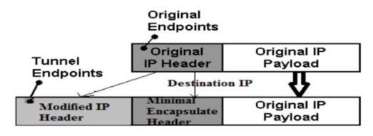
2. Minimal Encapsulation
More efficient than IP-in-IP as it avoids duplicating some fields
Reduces overhead by eliminating redundant information from the inner header
Still maintains the essential routing information
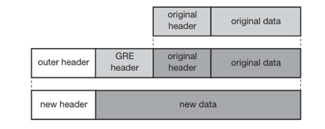
3. Generic Routing Encapsulation (GRE)
More versatile encapsulation method (RFC 1701, RFC 2784)
Includes additional fields in the GRE header:
Checksum (optional)
Protocol type
Key (optional)
Sequence number (optional)
Routing information (optional)
Offset (optional)
Allows encapsulation of various protocol packets
More flexible but includes more overhead
Each encapsulation technique offers different trade-offs between overhead, flexibility, and complexity. IP-in-IP is simpler and required by the Mobile IP standard, while GRE offers more features but with additional overhead. The choice depends on specific network requirements and constraints.
Explain agent registration process in mobile communication.
Agent Registration process in mobile communication
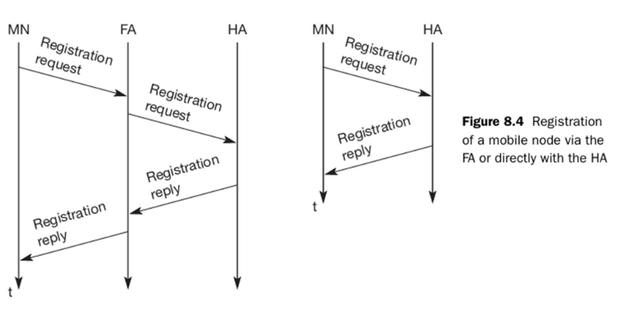
Agent registration is the process by which a Mobile Node (MN) registers its presence in a foreign network with its Home Agent (HA) through a Foreign Agent (FA). This allows the HA to forward packets to the MN’s current location.
Agent Registration Process in Mobile Communication:
FA advertises its presence to nearby Mobile Nodes (MNs).
MN detects it’s in a foreign network and obtains a Care-of Address (COA).
MN sends a Registration Request to the Home Agent (HA) via the Foreign Agent (FA) or directly.
FA forwards the request to HA if it’s not a direct registration.
HA verifies the request and updates its mobility binding table with MN’s COA.
HA sends a Registration Reply back to the FA or MN indicating success/failure.
FA (if used) forwards the reply to the MN.
MN receives the reply and starts receiving tunnelled packets at the COA.
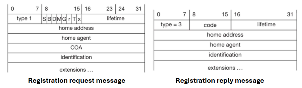
Registration Message Fields (Request & Reply)
• Type:
1 for Registration Request
3 for Registration Reply
• Lifetime:
Indicates the time duration of registration.
In Request: Requested by the Mobile Node.
In Reply: Granted by the Home Agent.
• Home Address:
Permanent IP address of the Mobile Node (MN). Must match in both Request and Reply.
• Home Agent:
IP address of the Home Agent (HA) responsible for the MN.
• Identification:
Unique value used to prevent replay attacks. Must match between Request and Reply.
• Extensions:
Optional fields for authentication or additional information.
• Flags (in Request only):
Control bits like S, B, D, M, G, r, T, x.
Enable features such as simultaneous bindings, reverse tunnelling, etc.
• Care-of Address (COA) (Request only):
Temporary IP address where the MN is currently located (in the foreign network).
• Code (Reply only):
Indicates registration status (e.g., success, denial, or error type).
Reverse tunneling is a mechanism in Mobile IP that enables packets sent by a Mobile Node (MN) to be routed through its Home Agent (HA) before reaching their final destination. This is the opposite direction of the standard tunneling process, hence the name “reverse tunneling.”
Basic Concept
In standard Mobile IP operation, packets from a Correspondent Node (CN) to a Mobile Node are tunneled from the Home Agent to the Foreign Agent, but packets from the Mobile Node to the Correspondent Node are sent directly. Reverse tunneling changes this by:
Having the Mobile Node send packets to the Foreign Agent
The Foreign Agent encapsulates these packets and tunnels them to the Home Agent
The Home Agent decapsulates the packets and forwards them to their final destination
Purpose and Benefits
Reverse tunneling addresses several important issues in mobile communications:
Topological Correctness:
Many routers and firewalls reject packets with source addresses that don’t match their expected network topology
Packets encapsulated by the Foreign Agent have topologically correct addresses
This prevents packet filtering by intermediate firewalls that check source addresses
TTL Problems:
Time-to-Live (TTL) values can be incorrect when the Mobile Node is far from its home network
Reverse tunneling ensures proper TTL values in the home network
Multicast Support:
Facilitates multicast operations that depend on source address verification
Security and Network Access:
Allows Mobile Nodes to access private networks with strict ingress filtering
Maintains appearance that all traffic is originating from the home network
Selective retransmission (also known as Selective Acknowledgment or SACK) is an enhancement to standard TCP that improves efficiency when handling packet loss, particularly in wireless and mobile environments.
The Problem with Standard TCP
In standard TCP, when a packet is lost, the sender must retransmit that packet and all subsequent packets, even if those subsequent packets were successfully received. This is because traditional TCP uses cumulative acknowledgments that only confirm receipt of all bytes up to a certain sequence number.
For example, if packets 1, 2, 4, and 5 arrive but packet 3 is lost:
The receiver can only acknowledge up to packet 2
After timeout or triple duplicate ACKs, the sender must retransmit packet 3 and all subsequent packets (4 and 5)
This wastes bandwidth and reduces throughput, especially on wireless networks
Selective Retransmission Mechanism
Selective retransmission solves this inefficiency by:
Allowing the receiver to inform the sender about all segments that have arrived successfully, including those that arrived after a missing segment
Enabling the sender to retransmit only those segments that have actually been lost rather than retransmitting all segments from the point of loss
How It Works
SACK Option Negotiation:
During TCP connection establishment, both ends indicate SACK capability
This is done through TCP options in the SYN packets
Acknowledging Received Segments:
When a gap in sequence numbers is detected, the receiver continues to send ACKs for the last in-order segment received
These ACKs include SACK blocks that specify which out-of-order segments have been successfully received
Selective Retransmission:
The sender maintains information about which segments have been selectively acknowledged
Only unacknowledged segments are retransmitted
This avoids unnecessary retransmission of data that has already been received
Benefits
Efficiency: Retransmits only lost data, saving bandwidth
Improved Throughput: Particularly beneficial in networks with high packet loss rates (like wireless networks)
Reduced Latency: Faster recovery from packet loss
Better Utilization: Makes better use of available network capacity
Implementation Considerations
Requires slightly more complexity in TCP implementation
Needs additional buffer space at both sender and receiver
Both sender and receiver must support the SACK option
The overhead of SACK information in ACK packets is minimal compared to the bandwidth saved
Selective retransmission represents one of the most important TCP enhancements for mobile networking, as it specifically addresses the inefficiencies of traditional TCP when dealing with the higher packet loss rates commonly encountered in wireless environments.
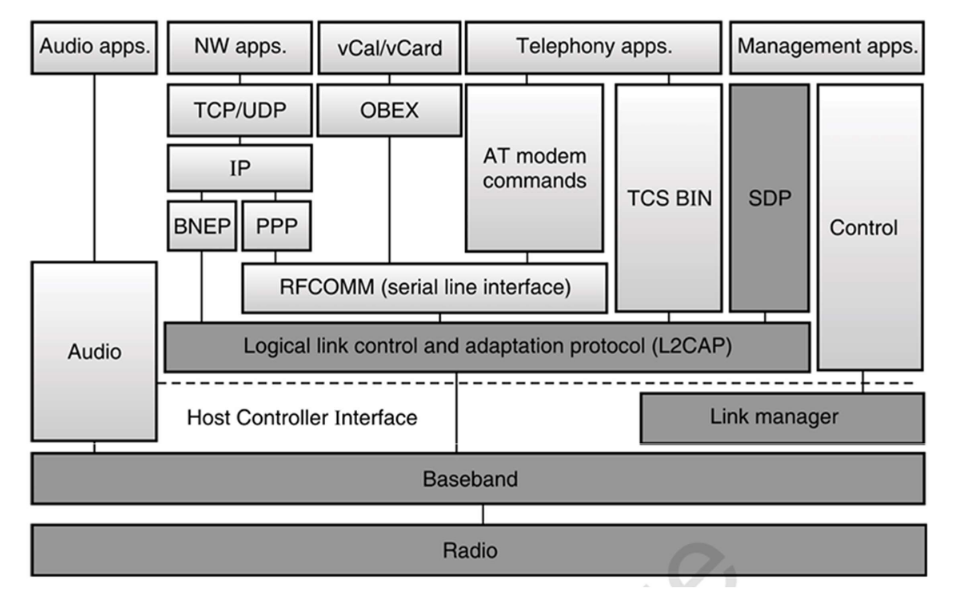
Explain the protocol architecture of IEEE 802.11 with diagram.
IEEE 802.11 Protocol Architecture
The IEEE 802.11 standard defines the protocol architecture for Wireless Local Area Networks (WLANs). It describes how data is transmitted and managed over wireless networks.
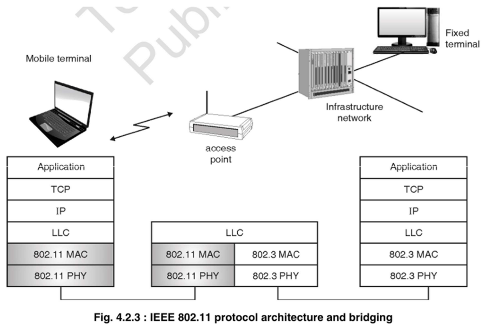
This architecture facilitates the connection of wireless devices to a wired network using WiFi (IEEE 802.11) through an Access Point (AP). The AP acts as a bridge between two networks:
Wireless (IEEE 802.11)
Wired Ethernet (IEEE 802.3)
Although these networks use different MAC and PHY layers, they share a common LLC layer, which enables communication. The AP translates between the two protocols, allowing devices on both networks to utilize the same TCP/IP applications for services like web Browse or email. This setup facilitates smooth communication in infrastructure-based wireless networks.
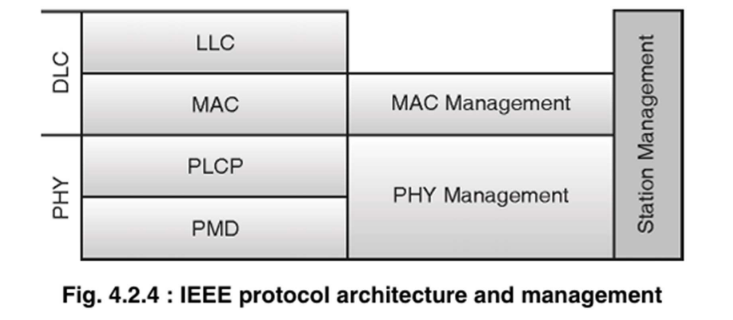
The IEEE 802.11 protocol architecture is typically described in terms of the following layers:
Physical Layer (PHY):
Responsible for wireless signal transmission and reception.
Defines modulation techniques (e.g., OFDM, DSSS) and data rates.
Divided into three sublayers:
PMD (Physical Medium Dependent): Responsible for the actual modulation and transmission of signals.
PLCP (Physical Layer Convergence Protocol): Prepares data for transmission and adds headers.
PHY Management: Coordinates the functions of the physical layer.
MAC Layer (Medium Access Control):
Manages channel access using mechanisms like CSMA/CA for collision avoidance and controls frame transmission.
MAC Management handles processes such as scanning, authentication, and association.
LLC Layer (Logical Link Control):
Provides flow and error control for data transmission.
Interfaces with higher network layers (e.g., TCP/IP).
Eavesdropping
Attackers use tools like Wireshark to intercept unencrypted wireless traffic and extract sensitive information.
Rogue Access Points
Malicious individuals set up unauthorized access points with SSIDs similar to legitimate networks. This tricks users into connecting and unknowingly exposing their credentials.
Man-in-the-Middle (MITM) Attacks
In MITM attacks, hackers intercept and manipulate data exchanged between two parties without their knowledge, potentially leading to data breaches.
Denial of Service (DoS) Attacks
Attackers flood the WiFi network with excessive traffic, causing it to slow down or crash, disrupting legitimate user access.
Passive Capturing
Attackers silently capture wireless packets without actively interfering. These captured packets are later analyzed to extract sensitive data like passwords or session tokens.
Configuration Problems
Incorrect or incomplete settings on wireless routers or access points such as open SSIDs or weak encryption can leave networks vulnerable to unauthorized access or easy exploitation.
Misbehaving Clients
Sometimes, clients unintentionally or intentionally connect to unauthorized WiFi networks. This behavior can expose both the user and organizational data to significant risks.
Wi-Fi security protocols are encryption standards used to secure data transmitted over wireless networks. Over the years, several protocols have been developed, each offering improvements over its predecessor.
1. WEP (Wired Equivalent Privacy)
Introduced: 1997 (as part of the original IEEE 802.11 standard)
Encryption: RC4 stream cipher
Key Length: 40-bit (original), extended to 104-bit
🔹 Features:
Designed to provide confidentiality comparable to wired networks.
Uses static keys for encryption.
🔻 Weaknesses:
Vulnerable to several attacks (e.g., IV reuse, key cracking).
Easily broken using tools like Aircrack-ng.
No longer considered secure.
2. WPA (Wi-Fi Protected Access)
Introduced: 2003 (as a temporary replacement for WEP)
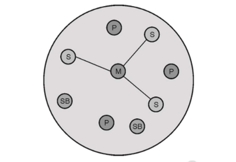
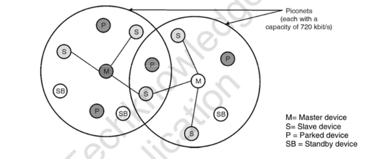
Bluetooth is a short-range wireless communication technology used to exchange data between devices over short distances using radio waves in the 2.4 GHz ISM band.
Key Features:
Range: Typically up to 10 meters (can extend to 100m with Class 1 devices).
Data Rate: Up to 2-3 Mbps (depending on version).
Frequency Hopping: Uses Frequency-Hopping Spread Spectrum (FHSS) to reduce interference.
Low Power: Designed for low energy consumption, ideal for portable and battery-operated devices.
Common Applications:
Wireless headphones and speakers
File sharing between smartphones
Bluetooth keyboards and mice
Smartwatches and fitness trackers
Car infotainment systems
Security:
Includes pairing, authentication, and encryption.
Bluetooth Low Energy (BLE) adds better power efficiency and security.
Versions:
Bluetooth 1.0 to 3.0: Basic data transfer.
Bluetooth 4.0: Introduced Bluetooth Low Energy (BLE).
Bluetooth 5.0+: Increased range, speed, and support for IoT.
Bluetooth has become a key technology in personal area networking (PAN), making everyday device interactions seamless and wireless.
HIPERLAN (High Performance Radio LAN) is a set of wireless communication standards developed by the European Telecommunications Standards Institute (ETSI) to provide high-speed wireless networking, similar to Wi-Fi (IEEE 802.11).
Key Features:
Designed for high-speed data transfer in wireless local area networks (WLANs).
Operates in the 5 GHz frequency band (less crowded than 2.4 GHz).
Offers data rates up to 54 Mbps (in HIPERLAN/2).
Supports multimedia traffic like voice and video due to QoS (Quality of Service) features.
Versions:
HIPERLAN/1 (1996):
Offered up to 20 Mbps.
Focused on ad-hoc networking (device-to-device).
Included advanced MAC features like power saving.
HIPERLAN/2 (2000):
Offered up to 54 Mbps.
Designed for infrastructure-based networking (like Wi-Fi).
Supported integration with IP, ATM, and UMTS networks.
Limitations:
Complex protocol stack compared to Wi-Fi.
Failed to gain widespread adoption, as IEEE 802.11 (Wi-Fi) became the global standard.
Limited hardware support and industry backing.
Summary:
HIPERLAN was an early European attempt to standardize high-speed wireless LANs, offering advanced features but ultimately overshadowed by the global success of Wi-Fi.
What is the responsibility of MAC management in IEEE 802.11?
MAC management in IEEE 802.11
In IEEE 802.11 (Wireless LAN), MAC Management is responsible for controlling and managing how devices communicate and stay connected within the network.
The key responsibilities of MAC Management include: synchronization, power management, association/reassociation, and maintaining the MAC Management Information Base (MAC MIB).
1. Synchronization
In a wireless LAN, all stations (devices) must stay synchronized to ensure proper communication.
Access Points (APs) send out beacon frames at regular intervals.
These beacons contain timing information that helps stations adjust their clocks and maintain timing alignment.
This is crucial for timing operations like sleep/wake cycles in power-saving modes.
2. Power Management
Allows devices to conserve battery by entering low-power (sleep) mode when not transmitting or receiving.
Stations can inform the AP when they enter power-saving mode.
During this time, the AP buffers any incoming data for the sleeping device.
Devices periodically wake up to check for buffered data (via beacon frames).
3. Association / Reassociation
Association: The process where a station connects to an AP to gain access to the network.
Involves exchanging association request/response frames.
The AP assigns an Association ID (AID) to the station.
Reassociation: Happens when a mobile station moves from one AP’s range to another.
Ensures seamless handoff and continuous connectivity (important for roaming).
4. MAC Management Information Base (MAC MIB)
It is a database of parameters and status information maintained by each station or AP.
Cellular IP (CIP) is a micro-mobility protocol designed to complement Mobile IP by handling local mobility within a limited geographical area, such as a campus or metropolitan network. It is optimized for environments with a high density of mobile devices that frequently change their points of attachment to the network, such as in cellular networks or wireless LANs.
Key Components of Cellular IP
Cellular IP Gateway (GW)
Acts as the interface between the Cellular IP network and the broader Internet.
The gateway’s IP address serves as the care-of-address (COA) for all mobile hosts (MHs) attached to the network.
Base Stations (BS)
Serve as access points for mobile hosts.
Replace traditional IP routing with Cellular IP routing and location management.
Communicate with mobile hosts via wireless interfaces and route IP packets within the Cellular IP network.
Mobile Hosts (MH)
Devices that move within the Cellular IP network while maintaining connectivity.
How Cellular IP Works
Routing Mechanism
Uplink Packets:
Originate from the mobile host and are routed hop-by-hop to the gateway.
The path taken by these packets is cached in base stations (routing cache).
Downlink Packets:
Addressed to a mobile host and routed using the reverse path stored in the routing cache.
Paging Mechanism
Idle Mobile Hosts:
Hosts that have not received data packets for a system-specific time.
Their downlink routes timeout and are removed from the routing cache.
These hosts periodically send paging-update packets (empty IP packets addressed to the gateway) to maintain their presence in the paging cache.
Active Mobile Hosts:
Maintain entries in both routing and paging caches.
Periodically send route-update packets to keep their routing cache mappings valid.
Handover Process
Mobile-Controlled Handover (MCHO):
Initiated by the mobile host based on signal measurements from base stations.
Semi-Soft Handover:
During handover, downlink packets are temporarily delivered through both the old and new base stations to minimize packet loss.
Mappings for the old base station timeout and are cleared automatically.
Advantages of Cellular IP
Efficient Location Management:
Separates idle and active hosts, reducing unnecessary signaling overhead.
Flexible Handover:
Supports seamless handover with minimal packet loss.
Scalability:
Handles large numbers of mobile hosts by leveraging localized routing and paging.
Simplicity:
Mobile hosts are memory-less and rely on the network for routing and paging.
Global Migration Support:
Works alongside Mobile IP to provide both local and global mobility solutions.
Use Cases of Cellular IP
Wireless Campus Networks:
Provides seamless mobility for users moving between access points within a university or corporate campus.
Cellular Networks:
Enhances mobility management for mobile devices in cellular systems, reducing latency during handovers.
Internet of Things (IoT):
Supports efficient mobility for IoT devices in industrial or smart city environments.
Conclusion
Cellular IP is a robust and scalable solution for managing micro-mobility in IP networks. By leveraging localized routing, paging, and semi-soft handovers, it ensures seamless connectivity for mobile hosts while minimizing signaling overhead. Its integration with Mobile IP makes it a versatile choice for modern wireless networks.
What is micro mobility, its need and its approaches?
Micro mobility
Micro-mobility manages the seamless movement of mobile devices within a local or regional network, ensuring low-latency handovers within a single administrative domain. It is crucial for real-time applications like VoIP, online gaming, and video streaming.
Need for Micro-Mobility
Reduces Handover Latency
Ensures faster handover between access points.
Scalable Signalling
Limits signalling to the local network, reducing global routing updates.
Efficient Resource Usage
Avoids overload on global mobility protocols like Mobile IP.
Three major protocols are Cellular IP, HAWAII, and HMIPv6.
Cellular IP
Cellular IP is a micro-mobility protocol designed for the seamless movement of mobile nodes within an IP-based network. Unlike global mobility protocols, it optimizes local handovers using a routing cache, ensuring uninterrupted connectivity with minimal overhead.
Advantages of Cellular IP:
Seamless Local Handover: Maintains uninterrupted connectivity by using a routing cache during node movement.
Low Overhead: Optimizes local handovers without relying on global mobility protocols.
HAWAII (Handoff-Aware Wireless Access Internet Infrastructure)
HAWAII implements a hierarchical mobility management approach to enhance efficiency. By localizing handover processes, it minimizes global signalling overhead, making it ideal for scalable and efficient micro-mobility management.
Advantages of HAWAII:
Reduced Global Signalling: Localizes handover processes to minimize signalling overhead.
Scalability: Well-suited for large networks due to its hierarchical structure.
Hierarchical Mobile IPv6 (HMIPv6)
HMIPv6 is an advanced extension of Mobile IPv6 that introduces a dual-level mobility management system. By segmenting handovers into local and global domains, HMIPv6 significantly reduces signalling traffic, improves handover speed, and enhances network performance for mobile users.
Advantages of HMIPv6:
Improved Handover Speed: Segregates local and global domains for faster handovers.
Lower Signalling Traffic: Reduces global network load by handling updates locally.
IPv6 (Internet Protocol version 6) is the successor to IPv4, designed to address the limitations of its predecessor, particularly the exhaustion of IPv4 addresses. It uses a 128-bit address format, providing a vastly larger address space (approximately 3.4 × 10³⁸ addresses) compared to IPv4’s 32-bit system.
Key Features of IPv6:
Larger Address Space: Eliminates the need for NAT (Network Address Translation) by providing unique addresses for all devices.
Simplified Header Format: Improves routing efficiency by reducing header overhead.
Built-in Security: Supports IPsec for encryption and authentication, enhancing data security.
Auto-configuration: Allows devices to generate their own IP addresses (stateless address autoconfiguration).
Better Mobility Support: Optimized for mobile devices with features like Mobile IPv6 (MIPv6).
Flow Labeling: Enables QoS (Quality of Service) for real-time applications like VoIP and video streaming.
Advantages Over IPv4:
No more address exhaustion.
Improved multicast and anycast support.
Reduced reliance on DHCP.
Enhanced performance with fewer header fields.
IPv6 is essential for the future of the Internet, supporting the growing number of connected devices in IoT, 5G, and cloud computing. However, its adoption is gradual due to compatibility challenges with legacy IPv4 systems.
IPv6 Header
The IPv6 header is a simplified and more efficient version of the IPv4 header, designed to improve routing performance and support modern networking needs. It has a fixed size of 40 bytes (compared to IPv4’s variable-length header) and consists of the following fields:
IPv6 Header Structure
Field
Size (bits)
Description
Version
4
Identifies IPv6 (value 6).
Traffic Class
8
Replaces IPv4’s ToS (Type of Service) field; used for QoS prioritization (e.g., VoIP, video).
Flow Label
20
Identifies packets belonging to the same flow for real-time traffic handling.
Payload Length
16
Indicates the size of the payload (data) following the header.
Next Header
8
Specifies the type of the next header (e.g., TCP=6, UDP=17, or an extension header).
Hop Limit
8
Similar to IPv4’s TTL; decremented by each router; packet is dropped if it reaches 0.
Source Address
128
IPv6 address of the sender.
Destination Address
128
IPv6 address of the receiver.
Key Improvements Over IPv4
Simplified Format:
Fixed-length header (40 bytes) for faster processing.
No checksum (reduces router overhead).
Fragmentation handled via Extension Headers (not in the main header).
Extension Headers:
Optional headers (e.g., Routing, Fragmentation, Authentication) are chained via the Next Header field.
Better QoS Support:
Flow Label enables efficient handling of real-time traffic (e.g., video streaming).
No Broadcasts:
Uses multicast and anycast instead, reducing network congestion.
Example IPv6 Header
+-+-+-+-+-+-+-+-+-+-+-+-+-+-+-+-+-+-+-+-+-+-+-+-+-+-+-+-+-+-+-+-+|Version | Traffic Class | Flow Label |+-+-+-+-+-+-+-+-+-+-+-+-+-+-+-+-+-+-+-+-+-+-+-+-+-+-+-+-+-+-+-+-+| Payload Length | Next Header | Hop Limit |+-+-+-+-+-+-+-+-+-+-+-+-+-+-+-+-+-+-+-+-+-+-+-+-+-+-+-+-+-+-+-+-+| |+ Source Address +| |+-+-+-+-+-+-+-+-+-+-+-+-+-+-+-+-+-+-+-+-+-+-+-+-+-+-+-+-+-+-+-+-+| |+ Destination Address +| |+-+-+-+-+-+-+-+-+-+-+-+-+-+-+-+-+-+-+-+-+-+-+-+-+-+-+-+-+-+-+-+-+
Conclusion
The IPv6 header is optimized for efficiency, scalability, and modern networking demands, eliminating IPv4’s limitations while supporting advanced features like mobility, security, and QoS. Its streamlined design ensures faster routing and better performance in large-scale networks.
Mobility management enables mobile devices (Mobile Nodes - MNs) to maintain uninterrupted internet connectivity while moving across different networks without changing their IP addresses. This is achieved through IP mobility protocols that handle seamless handovers between networks.
Mobile IP (IP Mobility)
Mobile IP allows a device to have:
Home Address (HoA): Permanent IP address in its home network.
Care-of Address (CoA): Temporary IP address in a foreign network.
How Mobile IP Works
The MN registers its CoA with the Home Agent (HA).
The HA intercepts packets destined for the MN’s HoA and tunnels them to the CoA.
The MN sends replies either directly or via reverse tunneling.
Challenges in Mobile IP
Triangular Routing (MIPv4): Packets must go through the HA, increasing latency.
Handover Delay: Registration and binding updates cause interruptions.
Macro Mobility (Inter-Domain Mobility)
Manages movement across different administrative domains (e.g., between ISPs).
1. Mobile IPv6 (MIPv6)
Enhances IPv6 with built-in mobility support.
Eliminates triangular routing by allowing direct communication between the MN and Correspondent Node (CN).
Uses Binding Updates (BU) to inform CNs of the MN’s current location.
2. Fast Mobile IPv6 (FMIPv6)
Reduces handover latency by:
Predicting movement (using Layer 2 triggers).
Pre-configuring a new CoA before disconnection.
Buffering packets to prevent loss during handover.
Micro Mobility (Intra-Domain Mobility)
Manages movement within the same network domain (e.g., campus, enterprise network).
1. Cellular IP (CIP)
Uses gateway-based routing and paging caches.
Soft-state routing: Caches paths for active/idle MNs.
Semi-soft handover: Temporarily uses both old and new base stations to minimize packet loss.
2. HAWAII (Handoff-Aware Wireless Access Internet Infrastructure)
Hierarchical routing: Updates paths only along the MN’s route.
Reduces signaling overhead by avoiding global HA updates.
3. Hierarchical MIPv6 (HMIPv6)
Introduces a Mobility Anchor Point (MAP) to manage local movements.
The MN has two addresses:
Regional CoA (RCoA) – For global routing.
On-Link CoA (LCoA) – For local routing.
Reduces binding updates to the HA.
Conclusion
Mobile IP enables global mobility by maintaining a permanent HoA while using temporary CoAs.
Macro Mobility (MIPv6/FMIPv6) handles large-scale movements across networks.
Micro Mobility (CIP/HAWAII/HMIPv6) optimizes local handovers for faster, seamless connectivity.
These protocols ensure that wireless devices stay connected while moving, supporting applications like VoIP, video streaming, and IoT in 5G and Wi-Fi networks.
What do you mean by Self Organizing Network. Explain the architecture of SON
Self Organizing Network
A Self-Organizing Network (SON) is an advanced automation framework used in modern mobile networks (such as LTE and 5G) to reduce manual intervention by enabling the network to automatically configure, optimize, and heal itself.
Key Functions of SON
Self-Configuration: Automatically configures newly deployed network nodes (like base stations) for plug-and-play operation.
Self-Optimization: Continuously improves performance by adjusting network parameters (e.g., handover thresholds, power levels).
Self-Healing (Self-Recovery): Detects and corrects faults (e.g., base station failure) by reconfiguring surrounding nodes.
🏗 Architecture of SON
SON can be implemented using three types of architectures:
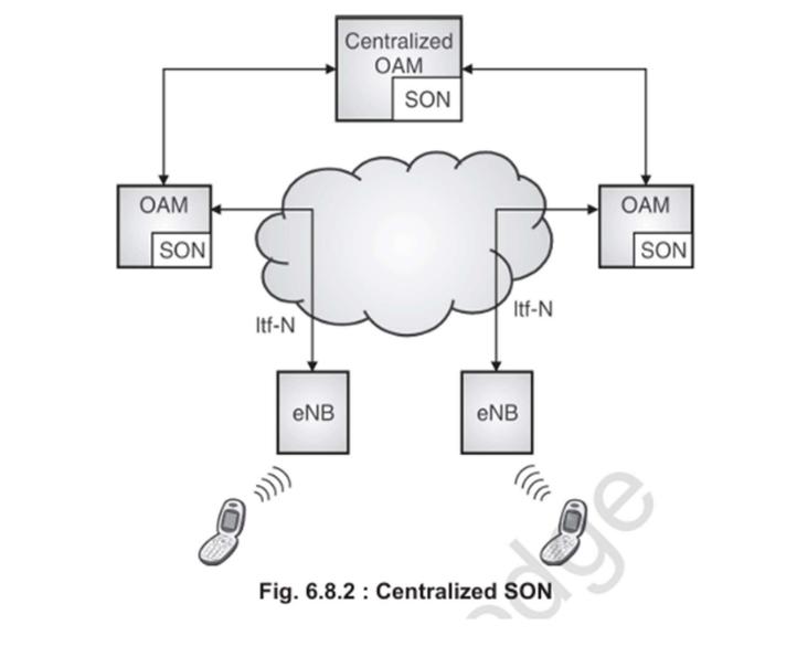
1. Centralized SON
Location: All SON functionalities are located in a central OAM (Operations, Administration, and Maintenance) system.
Function: Global optimization (e.g., network-wide load balancing, interference coordination).
Advantage: Complete network view allows for coordinated, intelligent decisions.
Limitation: Slower response and potential scalability issues.
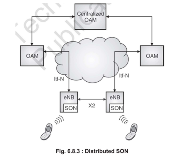
2. Distributed SON
Location: SON functions are embedded directly into each base station (e.g., eNB in LTE).
Function: Each base station performs local optimizations like handover tuning and power adjustment.
Advantage: Fast response time and scalability.
Limitation: Lack of global network awareness may lead to suboptimal decisions.
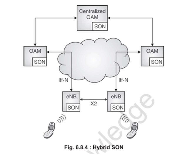
3. Hybrid SON
Location: Combines both centralized and distributed components.
Function:
Central SON handles global, complex tasks.
Distributed SON handles fast, local optimizations.
Advantage: Balances efficiency, speed, and performance.
In Summary:
SON is essential for handling the increasing complexity and scale of mobile networks. It enhances network performance, improves user experience, reduces operational costs, and supports rapid deployment of new network nodes.
Explain self-organizing networks(SON) for heterogeneous networks.
Self-organizing networks(SON) for Heterogeneous Networks
Self-Organizing Networks (SON) for Heterogeneous Networks (HetNets) refer to intelligent network automation mechanisms that manage and optimize complex, multi-layered mobile networks consisting of different cell types, radio technologies, and backhaul solutions. As mobile data demand increases, especially with high-resolution video streaming, social media, and IoT, SON becomes critical to ensure efficient operation and improved user experience.
What is a Heterogeneous Network (HetNet)?
A HetNet is a mobile network that includes:
Multiple Radio Access Technologies (RATs) such as LTE, 5G, Wi-Fi, and legacy systems like 3G.
Various types of cells including macro, micro, pico, and femto cells.
Diverse backhaul connections like fiber, microwave, and wireless links.
Role of SON in HetNets
SON in HetNets enables the network to self-manage its complex environment, addressing challenges such as interference, mobility, load balancing, and resource allocation. The key functions of SON in HetNets are:
Self-Configuration:
Automates the setup of new cells, including small cells and femtocells.
Ensures seamless integration with existing macro cells and other technologies.
Self-Optimization:
Dynamically adjusts parameters such as handover thresholds and transmission power.
Optimizes performance in dense, layered environments with overlapping cell coverage.
Supports load balancing across different RATs and cell types.
Self-Healing:
Detects cell failures or performance degradation.
Reconfigures neighboring cells to compensate for the affected area.
Benefits of SON in HetNets
Improved Coverage and Capacity: Enhanced signal quality and resource utilization.
Interference Management: Automated coordination between overlapping cells.
Reduced Operational Cost: Minimizes the need for manual intervention.
Faster Deployment: New nodes can be automatically configured and integrated.
Enhanced User Experience: Maintains consistent service quality across different technologies and cell types.
In conclusion, SON plays a vital role in managing the complexity of heterogeneous networks by automating configuration, optimization, and recovery tasks, leading to a more robust, scalable, and efficient mobile network infrastructure.
VoLTE is a technology that allows voice calls to be made over the LTE network using an all-IP framework, replacing traditional circuit-switched calling. It offers high-definition voice quality, faster call setup, and allows simultaneous use of voice and data services.
How VoLTE Works: Call Flow
Call Setup: The user equipment (UE) registers with the IMS core using SIP to initiate the call.
Media Transport: Voice is transmitted using RTP over the LTE data channel.
Call Handover: If LTE signal weakens, the call is handed over to 3G via SRVCC.
Call Termination: The session ends when either party disconnects.
Advantages
High-definition (HD) voice quality
Simultaneous voice and data usage
Faster call setup times
Lower call drop rates
Challenges
Requires LTE network coverage
Works only on VoLTE-capable devices
This makes VoLTE an essential component of modern mobile networks, especially in LTE and 5G deployments.


/../../Notes/attachments/Pasted-image-20250519234035.png)
/../../Notes/attachments/Pasted-image-20250519234059.png)
Steps:
Steps: